

The relay wiring diagram is not as bad as it looks. A relay is simply an electrically operated switch – it uses a small current from your cab switch to control a larger one for lights, fans, or horns. The pins follow a standard pattern, and once you learn it, you can wire up just about anything. A 4-pin relay switch gives you one power output. A 5-pin gives you a second one that works in reverse—it is on when the relay is off. This guide covers wiring both types for loaders, excavators, and skid steers.
How to Wire 4-Pin and 5-Pin Relays?
This section covers both relay types. The quick wiring layouts below show you how to connect everything for common off-road accessory installs.
4-Pin Relay Wiring
Use a 4-pin relay when you just need to turn one device on with a switch – for example, rear work lights, an auxiliary cooling fan, or a warning beacon.
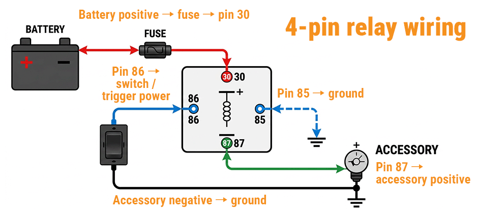
Wiring layout:
- Pin 85 → ground (chassis or battery negative)
- Pin 86 → switched +12V from your cab switch
- Pin 30 → battery +12V via an inline fuse (place the fuse as close to the battery as possible)
- Pin 87 → positive wire of your accessory
The accessory’s ground wire goes directly to chassis ground – do not run it through the relay.
Real example: Adding rear work lights on a loader
- Run fused battery power to pin 30.
- Run pin 87 to the light’s positive lead.
- Ground the light’s negative lead to the frame.
- Connect your cab switch to pin 86 (the other switch terminal gets +12V ignition power).
- Ground pin 85.
- Flip the switch – the relay clicks, pin 30 connects to 87, and the lights come on bright and steady.
Recommended parts for a durable install:
- Relay and socket kit (prevents loose connections)
- Electrical fuse holder with the correct amp rating
- Toggle switch or rocker switch
5-Pin Relay Wiring
A 5-pin relay works exactly like a 4-pin relay, except it adds pin 87a – an output that is powered when the relay is off.
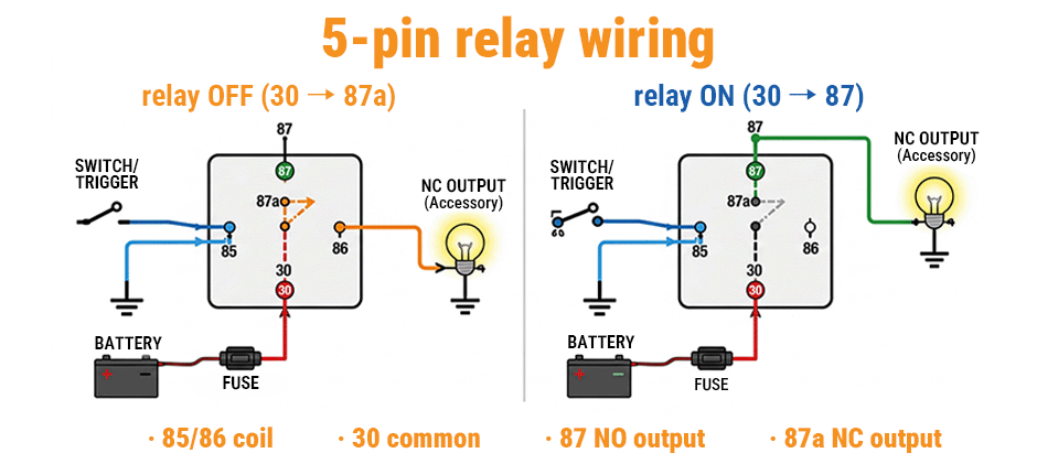
Wiring layout:
- Pin 85 → ground
- Pin 86 → switched trigger
- Pin 30 → fused battery +12V
- Pin 87 → output when the relay is on (normally open)
- Pin 87a → output when the relay is off (normally closed) – use this only if you need this function
When to use pin 87a:
Pin 87a is useful for changeover circuits – for example, switching between two different lights. In a standard 5-pin relay wiring diagram, this terminal is often left unused, but understanding it unlocks more advanced control options.
For most add-on accessories (lights, fans, horns), you simply leave 87a disconnected and treat the 5-pin relay exactly like a 4-pin.
Troubleshooting tip: If your accessory stays on all the time instead of switching with the trigger, you probably connected your load to 87a instead of 87. Move the wire to pin 87.
Which One Should You Choose?
| Relay Type | Pins | Best Application |
|---|---|---|
| 4-pin | 85, 86, 30, 87 | Simple on/off – work lights, fans, horns |
| 5-pin | 85, 86, 30, 87, 87a | Changeover circuits, or use as a 4-pin with 87a unused |
For most off-road accessory installations, a 4-pin relay is all you need. Choose a 5-pin relay only if you specifically require the normally closed feature.
What Do the Relay Pin Numbers Mean?
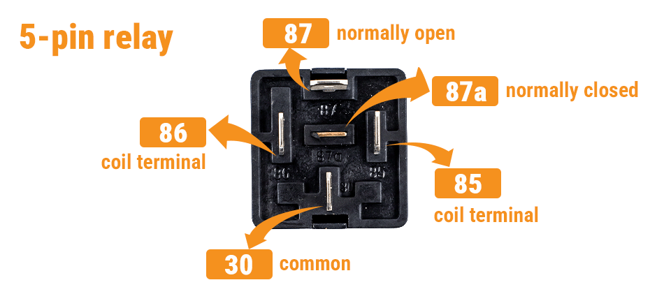
Almost all automotive-style relays follow the same DIN standard. Memorize this table once – you will refer back to it during wiring.
| Pin | Function | Typical Connection |
|---|---|---|
| 85 | Coil terminal | Ground (in most standard setups) |
| 86 | Coil terminal | Switched +12V trigger (in most standard setups) |
| 30 | Common terminal | Usually fed from battery positive through a fuse |
| 87 | Normally open (NO) output | Accessory positive wire (energized when relay is on) |
| 87a | Normally closed (NC) output | Accessory that needs power when relay is off (5-pin only) |
Important note on pins 85 and 86: In many standard relay setups, pin 85 is grounded, and pin 86 receives the switched positive trigger. However, some relays have non-polarized coils (85 and 86 can be swapped), while others include a flyback diode and require correct polarity – always check the relay datasheet or housing markings.
The coil is the part that does the work – when current flows through it, it creates a magnetic field strong enough to pull the internal contacts together.
Quick memory rule:
- 85 and 86 = control side (small wires are fine)
- 30, 87, and 87a = load side (use wire thick enough for your accessory)
A 4-pin relay simply has no 87a terminal – that is the only difference between the two types.
How Does a Relay Work?
Every relay has two separate relay circuits inside one small box. The control circuit (coil side) uses a tiny current to create a magnetic field. The load circuit (contact side) carries the heavy current for your accessory.
| Circuit | What It Does | Pins Involved |
|---|---|---|
| Control side (coil) | Uses a tiny current to create a magnetic field | 85 and 86 |
| Load side (switched) | Carries the heavy current for your accessory | 30, 87, (and 87a on 5-pin) |
Why this matters on off-road machinery – Your cab switch only needs to handle the small control current. The relay handles the big current for lights, fans, or horns. That means:
- Longer switch life
- Brighter lights (less voltage drop)
- Safer wiring (shorter high-current paths)
What Happens Inside When You Flip the Switch?
- You send a small trigger signal to the coil (pins 85 and 86).
- The coil energizes, pulling the internal contact.
- On a 4-pin relay: pin 30 connects to pin 87 – power flows to your accessory.
- On a 5-pin relay: the contact moves away from pin 87a (normally closed) and touches pin 87 (normally open).
Normally Open (NO) = the circuit between 30 and 87 stays open until the relay is energized.
Normally Closed (NC) = the circuit between 30 and 87a stays closed until the relay is energized (5-pin only).
Relay wiring diagram symbols like NO and NC become second nature once you’ve wired a few circuits.
Common Relay Wiring Mistakes
Avoid these frequent errors that cause no-start, no-power, or always-on circuits. Most of these mistakes happen when you skip reading the relay wiring diagram and just start connecting wires by memory.
- Connecting the load to 87a instead of 87 – the device runs constantly and will not switch off.
- Skipping the fuse – a short circuit can melt wires or cause a fire.
- Using wire or a fuse that is too small – size both based on the accessory’s actual current draw, not just the relay’s rated capacity. For example, a 30A relay with a 10A light only needs 14 AWG wire and a 15A fuse; the relay’s maximum rating is not the target.
- Poor grounding – a weak ground on pin 85 or the accessory leads to intermittent operation or dim lights.
- Assuming all relays have the same pin layout – always read the numbers printed on the relay housing, not the socket position. Different manufacturers may arrange pins differently.
Even a perfect wiring diagram will fail if the socket or fuse holder has a weak crimp. Use quality terminals and proper crimping tools. For everything else, check out our wiring and connections section.
5-Step Relay Wiring Checklist
Use this checklist when you are actually doing the installation.
- Confirm the relay type – Is it a 4-pin or 5-pin relay? Read the numbers printed on the housing, not the socket.
- Protect the power feed – Install the fuse as close to the battery as possible, sized for your accessory’s actual current draw.
- Build the control side – Connect pin 85 to ground and pin 86 to your switched trigger.
- Build the load side – Connect pin 30 to fused battery power and pin 87 to your accessory. Leave pin 87a unused unless your circuit specifically needs it.
- Test with a multimeter before final wiring – Verify:
- Battery voltage at pin 30
- Trigger voltage at pin 86 when the switch is on
- Good ground at pin 85
- Output voltage at pin 87 when switched on
After the circuit works correctly, secure the harness away from exhaust heat, sharp edges, and moving parts.
Final Words
A 4-pin relay works for most on/off jobs like lights and fans. A 5-pin relay adds pin 87a for changeover circuits. Fuse pin 30, ground pin 85, and connect your load to pin 87. Size the fuse and wire for your accessory’s current draw. For relay replacements or electrical repairs, FridayParts offers quality aftermarket parts at reasonable prices, with broad compatibility across heavy equipment brands.
