

Having the cable extended can be a really common issue on your lawn mower due to constant use. Sometimes it can lead to a break, making it quite tricky to push the throttle cable. When you run into issues like this, having a Briggs and Stratton throttle linkage diagram can help you better understand the area clearly. Let’s enjoy it!
What Is the Throttle Linkage?
A throttle linkage is a mechanism to connect the accelerator pedal to the carburetor or throttle body of an engine. It consists of rods, cables, and springs that work together to control the amount of air and fuel in the engine. If these parts are bent, disconnected, or stuck, your push mower won’t start or may only run at one speed. The throttle plate is basically the largest piece there in the throttle body. It is basically a butterfly valve in charge of regulating airflow. A throttle cable remains in many vehicles and allows communication of accelerator pedal motion. This part stays connected to the Briggs and Stratton throttle linkage so that it can rotate the plate in turn. Shop quality throttle cable here.
How Does Throttle Work on Briggs and Stratton?
The changes in load need to be detected. There are gears and flyweights right inside the crankcase. This helps control the engine speed basically. The air-fuel mixture from inside the engine gets controlled, and basically closes the throttle from that. As engine load increases, the spin of the crankshaft becomes slower.
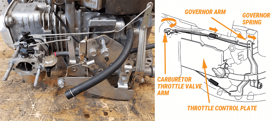
Briggs and Stratton Throttle Linkage Diagram
Linkage Briggs and Stratton Throttle Spring Diagram
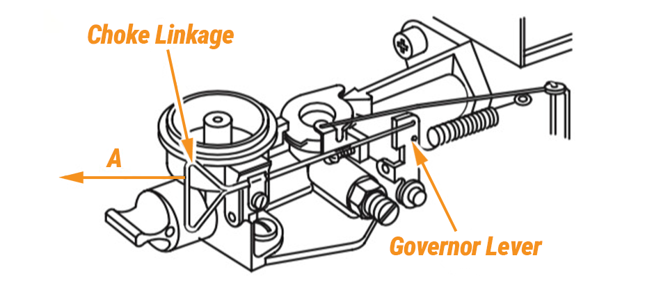
Choke-A-Matic Control System
This is a diagram for Briggs & Stratton Choke-A-Matic Control, which refers to a single-lever throttle and choke control or a pneumatic governor with manual choke linkage. When you push the throttle lever to the “Choke” or “Start” position, the system automatically closes the choke plate for cold starting. Once the engine starts, pulling the throttle lever slightly back will automatically open the choke plate.
- Choke Linkage/Link: A triangular loop or bent rod. When the throttle control cable is pulled to the left (Direction A), this linkage pushes the choke plate closed to assist with cold starting.
- Governor Link: A solid metal rod that connects the carburetor throttle lever (left end) directly to the hole on the governor lever (right end)
- Link Spring: The fine, thin spring wrapped around the solid governor link. It hooks into the exact same holes at both ends as the governor link to eliminate play/slop.
- Governor Spring: The heavier spring hooked below the governor arm, which provides the main tension for the governor system.
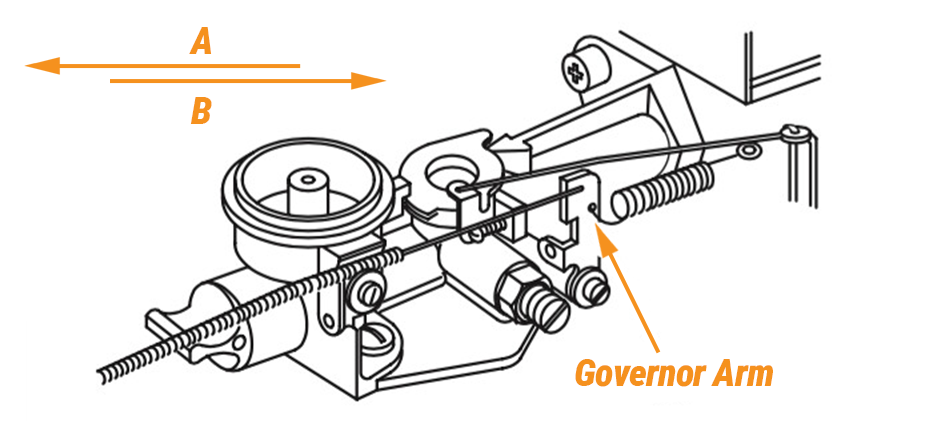
Pneumatic Governor Configuration with Long Link Spring
This is a diagram for a pneumatic governor configuration. Unlike the single-lever throttle and choke control, there is no choke link. Instead, it uses a very long, fine link spring that wraps entirely around the solid governor link.
- Governor Link & Long Link Spring: A solid metal rod (governor link) and the long outer spring (link spring) are hooked together at their right ends into the hole marked on the governor arm.
- Speed Control: The throttle control cable moves back and forth between Direction A (Fast) and Direction B (Slow). By moving in these directions, the cable pulls or releases this long spring, changing the tension applied to the governor arm to control engine speed.
How to Replace Briggs and Stratton Throttle Linkage?
Tools Required
To replace the throttle linkage on a Briggs and Stratton small engine, you will need the following tools. Since this job uses both inch and metric fasteners, it helps to know the correct SAE wrench size and keep an SAE-to-metric conversion chart nearby.
- 5/16 inch nut driver
- 10mm socket
- 10mm wrench
- T30 Torx bit
- Hose clamp
- Pliers
- Needle hose pliers
Step-by-Step Guide for Reference
Here are general steps for you to follow with your Part #693408.
Safety First
- Make sure the engine has cooled
- Keep the fuel tank empty or with little fuel (Recommended)
Remove the Old Throttle Linkage
- Unthread the screws securing the throttle cover plate with the nut driver
- Shift the throttle lever so you can detach the plate
- Use the socket to unthread the two front screws securing the fuel tank to the bracket
- Use the wrench to unthread the two rear screws securing the tank
- Use the hose clamp to prevent fuel from spilling out of the fuel line
- Use pliers to release the spring clamp so you can detach the fuel line from the carburetor and set the tank aside
- Use the nut driver to unthread the two mounting screws securing the air filter cover
- Remove the cover and the air filter
- Unthread the screws securing the filter base
- Pull the choke lever off so you can move the base out of the way
- Unthread the two mounting screws securing the carburetor, spacer, and gaskets with the T-30 Torx bit
- Unhook the throttle linkage and spring from the carburetor
- Fully detach the old throttle linkage and spring from the governor arm
Install the New Throttle Linkage
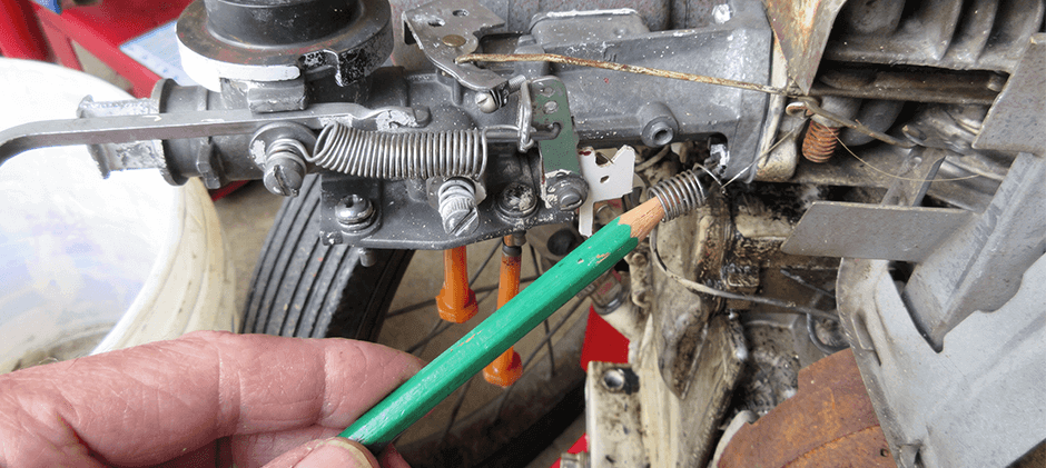
- Insert the spring aligned with the longer end of the linkage into the small hole in the governor arm – using needle-nose pliers will make this easier
- Insert the linkage into the governor arm with the spring in place
- Attach the opposite ends of the linkage and spring to the throttle lever on the carburetor
- Confirm the gasket and spacer are in place on the cylinder head
- Insert the two mounting screws through the carburetor and slide the carburetor gasket onto the screws
- Position the carburetor and thread the screws into the cylinder head
- Insert the two mounting screws through the base
- Align the base and thread the screws into the carburetor
Replace the Choke Lever
- Position the pre-cleaner in the cover and then the air filter with its rubber gasket facing out
- Align the cover on the base and secure it with the screws
- Reinstall the fuel tank by first reattaching the fuel line to the carburetor
- Secure it with the spring clamp and then remove the hose clamp
- Reposition the tank on the bracket and then rethread the rear and front screws
- Reposition the throttle cover plate and rethread the screws
- If necessary, refill the fuel tank and the engine should be ready for use
*Note: These step-by-step instructions are sourced from RepairClinic. Here is another video displaying the replacement instructions for your reference.
See related Briggs and Stratton Carburetor Diagram: A Complete Guide here.
Final Thoughts
Having a Briggs and Stratton throttle linkage diagram at least gives you the brief notes on the location of the carburetor parts and elements. With it, you can get things easier. If you are a person with patchy knowledge about the internal parts, you can also turn to a pro, who can give your mower throttle linkage a look and tell you exactly what the problem is with some notes. At FridayParts, you can explore a vast range of lawn mower carburetors and other related parts to get your mower back to its optimal performance.
