
The starter solenoid connects battery power to the starter motor and pushes the gear into the flywheel so the engine can crank. Once the engine starts, it disengages to protect the system. So, Diagram what wires go to the starter solenoid?
How Does a Solenoid Start Heavy Equipment?
A starter solenoid is basically a switch + a push device. When you turn the key to “start,” power goes to the solenoid coil. It creates a магнитic force and pulls a metal plunger inside. This happens fast and does two things at the same time:
- It pushes the starter gear forward to engage the flywheel
- It closes the circuit so battery power flows to the starter motor
Once power flows, the starter motor spins and turns the engine. After the engine starts, the gear pulls back. If you keep holding the key, a one-way clutch lets the gear free spin so the starter doesn’t get damaged.
Common starter types in heavy equipment
- Direct drive: Simple design. The motor and gear spin together.
- Gear reduction (more common): Uses internal gears to lower speed and increase torque.
Why gear reduction starters are preferred
- More torque: They can turn high-compression diesel engines, even in cold weather.
- More efficient: Use less power and are easier on the battery.
- More durable: Compact design. Handles vibration better in tough jobs.
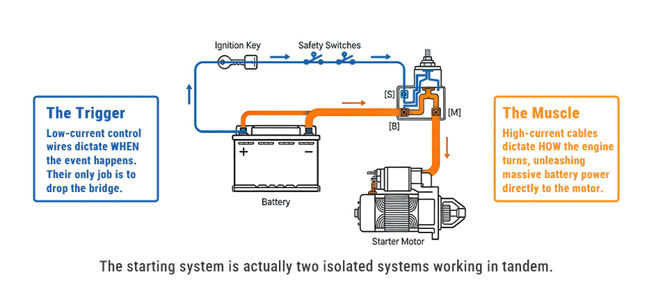
Mapping the “B,” “S,” and “M” Terminals
Precise identification of terminals is very important. Getting it wrong can lead to serious damage or even a fire. Most heavy equipment solenoids use a standard three-terminal setup, though some may have extra terminals.
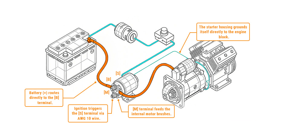
- The “B” (Battery) Terminal: This is the largest post on the solenoid. The positive battery cable connects here, and it always has power. In heavy equipment, this terminal should be kept clean and covered with a rubber boot to avoid accidental shorting.
- The “S” (Start) Termina: The “S” terminal is the trigger point. It is a smaller connector that gets the signal from the ignition switch or a starter relay. When it receives power, it activates the solenoid and moves the plunger.
- The “M” (Motor) Terminal: This terminal connects directly to the starter motor. Power only flows here when the solenoid is engaged and the internal contacts are closed.
- Auxiliary Terminals (R and I): In some setups, you may also see extra terminals. The “R” terminal is used to send a signal to a relay or help during cranking. The “I” terminal is mostly found in older systems and provides full battery voltage to the ignition system during startup.
| Terminal/Function | Common Wire Color(s) | Typical Gauge |
|---|---|---|
| Battery (B) | Red | AWG 4 or larger (2/0) |
| Start (S) | Yellow or Purple | AWG 10 or 14 (Control) |
| Motor (M) | Black | AWG 4 or larger |
| Relay (R) | Blue | AWG 14 (Control) |
| Ignition (I) | Brown | AWG 14 (Control) |
| Ground | Green or Bare | 3/4″ Tinned Strap |
Essential Tools and Safety Protocols for Heavy Equipment
We don’t use basic tools for heavy equipment wiring. The current is very high and can damage electronics or even cause burns.
Required tools
- Digital multimeter: Used to check voltage and grounding.
- High-leverage crimpers: Used to make strong, tight connections on control wires.
- Star washers and stainless bolts: Help cut through rust and keep a solid connection, even with vibration.
- High-strand cable: Flexible cable with many strands (like welding cable). It handles movement better and is less likely to break.
Safety rules
- Isolation: Always disconnect the negative battery cable first. This helps prevent short circuits.
- Machine position: Make sure the machine is in neutral or park. Lock all controls if needed.
- Work area: Keep the engine area clean. Oil or fuel mist can catch fire if there is a spark.
Pro tip
On job sites, dirt and moisture cause corrosion. After cleaning the connection, apply dielectric grease. It helps keep moisture out and prevents buildup that blocks current.
Step-by-Step Guide: Wiring the Starter Solenoid
Follow these steps to wire it right and get the machine ready to start.
- Connect battery to the B terminal: Run the main positive cable from the battery to the B terminal. Use a thick cable (like AWG 4 or 2/0). Tighten it well with a nut and washer.
- Connect the start signal to the S terminal: Hook up the control wire from the key switch or relay to the S terminal. AWG 10 or 14 works. For long machines like big excavators, AWG 10 is better to avoid voltage drop.
- Check the M terminal: Make sure the cable or strap to the starter motor is clean and tight. This carries all the power when the starter runs.
- Make a good ground connection: Ground is very important. Use a strong ground strap from the starter to the engine or frame. Make sure it’s clean and tight. Some setups use two ground straps for better reliability.
- Choose the right wire size: Use thick cables for the main power line. When the starter kicks in, it pulls a lot of current at once. If the wire is too small, it heats up and can damage the solenoid or wiring.
The “S” Terminal and the Neutral Safety Switch
On heavy equipment, the S terminal is part of the safety system. A neutral safety switch—and on newer machines, the ECM or BCM—controls whether the starter is allowed to work.
In modern machines, the key doesn’t send power straight to the starter. It sends a signal to the ECM first. The ECM checks that the machine is in neutral and the parking brake is on. Only then does it allow power to go to the S terminal.
This means troubleshooting is a bit different. If the machine won’t crank, check the safety system first. If there’s no voltage at the S terminal when you turn the key, the problem is usually the safety switch or the ECM—not the solenoid.
Troubleshooting and Diagnostic Testing
We use a digital multimeter to check a bad solenoid. On heavy equipment, common signs include rapid clicking (often from loose grounds due to vibration) or a whirring sound (the motor spins, but the gear doesn’t engage).
| Test Procedure | Technical Goal | Target Value |
|---|---|---|
| Earth Continuity Test | Resistance between motor frame and ground. | < 0.5 ohms |
| Insulation Resistance | Test for internal shorts at 500V. | Minimum 1 megohm |
| Voltage Drop Test | Measure loss across B and M contacts while cranking. | < 0.5V |
If your meter shows “OL” when testing the coil, it means the coil is broken.
If you see a voltage drop over 0.5V, the internal contacts are likely burned or worn out, and the solenoid should be replaced.
Common Mistakes to Avoid in Heavy Equipment Wiring
Even expert techs need to watch out for these common mistakes:
- Undersized Ground Paths: If the starter doesn’t have a heavy ground strap, electricity may flow through throttle cables or small sensor wires. This can melt wiring harnesses right away and even start a fire.
- Corrosion Overlay: Installing a new solenoid over painted or rusty mounting surfaces. Always grind the contact area down to clean, shiny metal first.
- Back-Feeding Current: On complex machines with dual solenoids, power can back-feed and keep the starter engaged. We fix this by using separate wiring or heavy-duty diodes in the control harness to make sure power only flows one way.
- Overtightening Terminals: Too much torque can crack the solenoid’s plastic cap, causing internal misalignment and letting moisture get inside.
Summary
By knowing the terminals and wiring them the right way, using a proper ground strap (like a tinned 150A strap), and choosing high-strand cables, you can protect your machine in tough job site conditions. At FridayParts, you can get high-quality starter solenoids that fit well and come at a good price—ready for demanding jobs.